Control your motors with L293D

***********************************************************************************************
update 26/4/09
***********************************************************************************************

My 1st instructable :)

http://www.instructables.com/id/HiTec-Servo-Hack/

***********************************************************************************************
***********************************************************************************************

After long research and trial and error, I´ve came up to a new walkthrough regarding this nice chip, the L293D.

Each project is one project and each one has its own unique power configurations, so you must be aware of the best battery choice and how to distribute voltage through your robot.

I strongly advice you to read the following articles:

Picking Batteries for your Robot
Once you’ve decided on batteries, how do you regulate the voltage

************************************************

L293D gives you the possibility to control two motors in both directions - datasheet
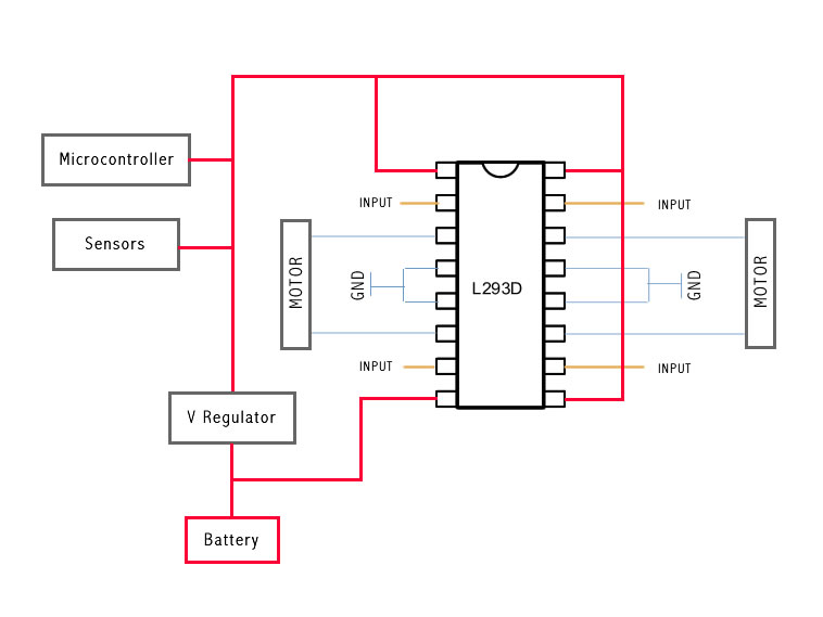
************************************************

The L293D Circuit:

Basic Implementation:

This is the most basic implementation of the chip.

As you can see, a 5V Voltage Regulator is between the battery and pins 1, 9, 16.

Pin 8 gets power before the VReg, if your motor needs for example 6V you should put 6V directly in this pin, all the other pins should not get more than 5V.

This will work with no problem at all, but if you want to do the right implementation take a look at the next example:

3235657956_b3be2b4f2f.jpg

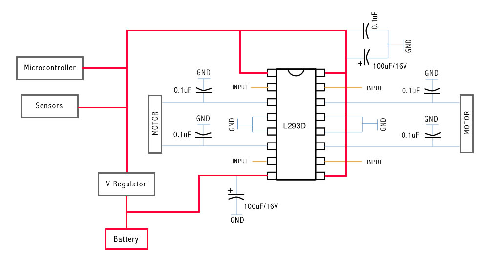
This is the correct Implementation (with the capacitors), and note that pin 8 is feeded by unregulated voltage. This means that if your motors need more than 5V, you should power this pin with that amount of voltage, and the rest of the circuit with 5V.

3235658022_f78495fddd.jpg


The capacitors stabilize the current.

The same circuit on a breadboard:

3252941552_2f4919475f.jpg

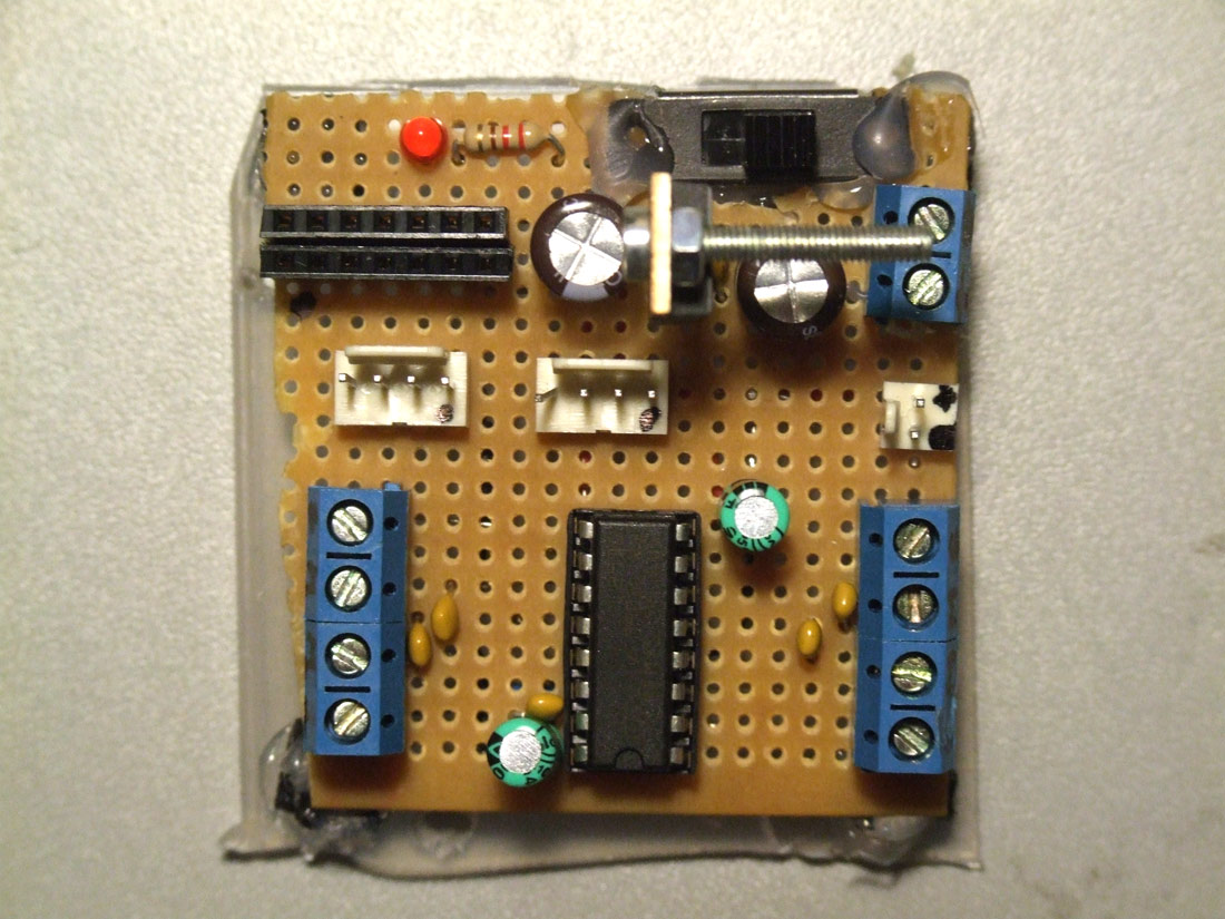
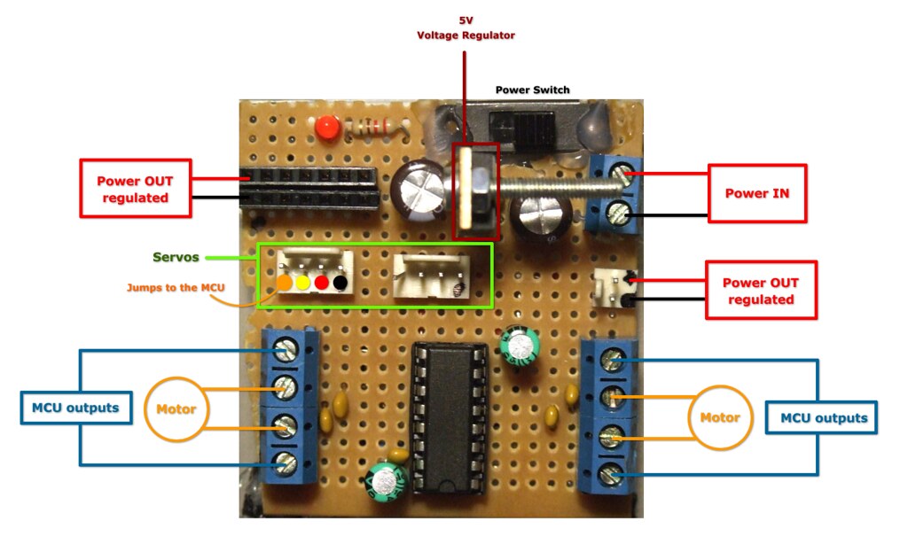
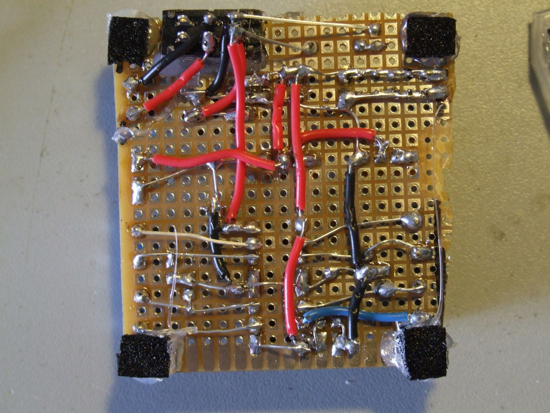
Soldered on a pcb and ready to go:

3234563157_780312a389.jpg


3451483356_2fdf26be19.jpg

3257970545_12de4f710e.jpg


This is the back of the circuit, click for high resolution photo.

***********************************************************************************************
CODE
***********************************************************************************************

// Use this code to test your motor with the Arduino board:

// if you need PWM, just use the PWM outputs on the Arduino
// and instead of digitalWrite, you should use the analogWrite command

// ————————————————————————— Motors
int motor_left[] = {2, 3};
int motor_right[] = {7, 8};

// ————————————————————————— Setup
void setup() {
Serial.begin(9600);

// Setup motors
int i;
for(i = 0; i < 2; i++){
pinMode(motor_left[i], OUTPUT);
pinMode(motor_right[i], OUTPUT);
}

}

// ————————————————————————— Loop
void loop() {

drive_forward();
delay(1000);
motor_stop();
Serial.println(”1″);

drive_backward();
delay(1000);
motor_stop();
Serial.println(”2″);

turn_left();
delay(1000);
motor_stop();
Serial.println(”3″);

turn_right();
delay(1000);
motor_stop();
Serial.println(”4″);

motor_stop();
delay(1000);
motor_stop();
Serial.println(”5″);
}

// ————————————————————————— Drive

void motor_stop(){
digitalWrite(motor_left[0], LOW);
digitalWrite(motor_left[1], LOW);

digitalWrite(motor_right[0], LOW);
digitalWrite(motor_right[1], LOW);
delay(25);
}

void drive_forward(){
digitalWrite(motor_left[0], HIGH);
digitalWrite(motor_left[1], LOW);

digitalWrite(motor_right[0], HIGH);
digitalWrite(motor_right[1], LOW);
}

void drive_backward(){
digitalWrite(motor_left[0], LOW);
digitalWrite(motor_left[1], HIGH);

digitalWrite(motor_right[0], LOW);
digitalWrite(motor_right[1], HIGH);
}

void turn_left(){
digitalWrite(motor_left[0], LOW);
digitalWrite(motor_left[1], HIGH);

digitalWrite(motor_right[0], HIGH);
digitalWrite(motor_right[1], LOW);
}

void turn_right(){
digitalWrite(motor_left[0], HIGH);
digitalWrite(motor_left[1], LOW);

digitalWrite(motor_right[0], LOW);
digitalWrite(motor_right[1], HIGH);
}

I still don’t understand why

I still don’t understand why you are only using one power source to power the motor driver AND the mincrocontroller. It looks like you are sharing 5 volts with the microcontroller and the motors. Shouldn’t you use 2 different power sources so the motors get a much higher voltage? The grounds should be shared between the two, but not the voltage (red line).

Also shouldn’t the resistor connect voltage to the LED not the LED to ground?

Maybe I’m wrong, feel free to correct me.

EDIT: I guess this does give the benefit of controlling the motor in both directions so it DOES achieve it’s goal. I just think the motors would be way underpowered.

The motors are underpowered

The motors are underpowered yes, they support until 6V. As soon as I make this with another setup I will post it.

As for the LED i guess you´re right! Thanks!

It shouldn’t make any
It shouldn’t make any difference, if you put the resistor before or after the LED. But it’s a matter of “clean” wiring to put the resistor in the “hot” line, because if you do a short circuit between the cathode and ground you will burn the LED. The other way nothing will happen :slight_smile:

Oh my, it is a tough world!

Oh my, it is a tough world! I was so glad that you made and shared this tutorial, and then all sorts of “why this and why that” :smiley: I hope you cope with that and keep it up so we can get a good base for all of us to build on. I plan to use it!

I haven’t got enough brains to see anything than it is a great tutorial :slight_smile: I know how much time you have put into making it, it is very consuming, so thanks.

no problem at all fritsl!!

no problem at all fritsl!! :smiley: I´m glad I could make this so far into the point I can share what I have learned!

I believe that the first thing one should note is… this works! May not be the "right way", but it works.

I believe there is a "right way" to do this techy things, but since every techy person has it´s own very opinion about the "right way" to do things, for me (arty person) if it works its perfect!! :smiley:

Please keep asking and giving feedback, so we all can learn and make this a better tutorial!! But please, let´s try to make this simple… :slight_smile:


Fun to watch, and learn from
Glad to see you got it going! It’s fun watching the behavior of robots, observing what they see, and are reacting to from what code we’ve used. Might be interesting to add more sensors, or maybe a speaker?

I’m not being critical at
I’m not being critical at all… I’m just trying to learn too :wink: If you don’t ask questions then that means you either understand it fully or don’t understand it at all (not even enough to form a question). I’m just very inquisitive!

**But I do ask questions… **
But I do ask questions… maybe in a compulsive way sometimes :slight_smile:

**hurry up on the breadboard tut. **

Hahaha. I really think i am gonna build it, where did you get those parts with the screws? thanks. amzaing. Five stars

Terminal Blocks
those parts are Terminal Blocks, you can get them in hardware and electronic shops :wink:

I use this "white bits"
I use this “white bits” instead of the male to female headers because they are better connectors. In the photo is the correspondent female bit, and to connect to the arduino pins I use male headers as you can see :slight_smile:

130925163_57652b137d.png


thanks, oh and sorry to bug
thanks, oh and sorry to bug you, but what are those white bits, and how do they plug into the arduino?

what are the female headers
what are the female headers for, I cant see where they would come in on the circuit diagram

Looking at the diagram you
Looking at the diagram you can see the "Microcontroller PWM Pins", and "Microcontroller Power" - this are the male headers ( in the foto they are the "white bits") and it is where you connect the female headers.

I´ve tested the LED and
I´ve tested the LED and resistor, and seen no diference in connecting the resitor to voltage, or to the ground.

But as DerDude said, it´s a good practice to put the resistor on the red wire before the LED.

Must correct the diagram.

thanks men, I understand
thanks men, I understand your explication. Thanks

I´ve updated pics and
I´ve updated pics and text :wink:

Thanks guibot for this

Thanks guibot for this tutorial, Also I would add that this works without changes for the SN754410 since it is pin-compatible with the L293D. I was able to do this in just a few minutes and it sure works better than my pololu controller. Now I know the h-bridge chip was OK, but the PIC was borked on that one :-/

:slight_smile:

**Thanks for the tutorial! **

Thanks for the tutorial! When I start playing with micro-controllers I’ll use it as a reference. Do you have expierence with the other controllers (Pic Axe, Pololu, Basic Stamp, or BOA’s favorite the PIC16F690)? How would you compare them with the Arduino?

Hopefully, this will not turn into another geek-tosterone laden “My PIC is better than yours” debate…