How to modify a micro servo for continuous rotation

Here is how I've modified cheap e-bay servo for continuous rotation,

Thanks to Oddbot for his explanations :)

Servo is a SG90 , equivalent to HXT900... and many others

Tools you will need : A sharp knife, a PH0 screwdriver, some sandpaper, soldering iron (or glue)

+ Nice to have : A microcontroller that continuously sets the servo to its center position ( 1.5 ms , position 150 on picaxe)

below : the package I recieved from Hong-Kong (about a week after the order was placed)

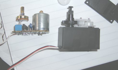
Step 1: Cut the stickers and remove the 4 screws

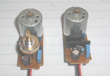
Step 2: Gently remove all the gears (remind that you will have to put them back !!!) and Pull the circuit away

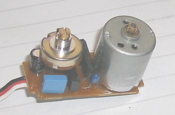
Step 3: Push the potentiometer out of its casing (as you can see, the output shaft is the potentiometer itself)

Step 4:

Connect the servo to your controller

The motor will rotate until you put the POT to its exact center position.

When the motor stops, you have found the good position, DO NOT disconnect the controller for the moment

Step 5 : SOLDER (yes SOLDER!) the shaft of the POT, from the back

Oddbot recommends to use hot-glue

If you decide to use glue, you will have to remove the white plastic cover sheet of the shaft-side, then fill with some glue

The shaft will never be able to move again, try to make sure... and power-off the controller if OK.

Then put the POT back to its casing

Step 6 : It's time to make the shaft thinner. (the outer gear as to turn freely)

I use sandpaper.

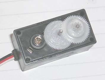
Step 7 : Cut the "stop finger" of the output gear

Step 8 : The finger is far away now, identify the 'notch' that prevents the gears to turn around its shaft.

Step 9 : I've used one of the screws to drill the notch out,

Then I've used the same screw to drill the plastic gear (Not sloppy on the shaft --> just be sure that it can turn with ease)

Step 10 : Put all the gears back to the shafts

Step 11 : You can put everything back together

Step 12: Write some code to test... and enjoy ;)

(note that servo0 is used to center the POT , and servo1 is used to test turning forward then backward for 3 seconds)

main:

servo 0,150

servo 1,100

pause 3000


servo 0,150

servo 1,150

pause 1000


servo 0,150

servo 1,200

pause 3000


servo 0,150

servo 1,150

pause 1000


goto main

Nice - and my extended tip

Not too sure how well the solder is going to hold on the pot spindle, though. Mine are made of steel or aluminium, neither of which solders. I suppose if you’ve thinned it enough that there’s absolutely no torque on it then the hardened flux might just be enough to stop it rotating.

I’ve tried a couple of other approaches. With the pot centering technique described above, I could never get all my continuous servo mods centered at exacly the same pulse width. Consequently, most of my small bots can’t go in a straight line.

One solution I tried was hacking the knob right off the pot (there was anough shroud let on the servo housing to be the load bearing of the main output shaft).

ServoModPot.jpg

The solution I ended up with was to desolder the pot altogether and replaced it with a pair of resistors in a fixed potential divider. They MUST be of a very low tolerance. If you use +/-5% pots, their resistances are too unpredictable and might be too substantially different. Try to get 0.5% or lower. They're more expensive (like 20 cents instead of 10!) and well worth it.

(Hahaha - I just realised after talking about ally and steel shafts (as in SOME of my servos) the ones in my picture have brass shafts. Brass, of course, solders particularly well!!- D'oh!)

I'll chuck in a few more pictures of my partially disassembled servos. This one might be useful if you can't rememeber the order the gears go back on:

ServoModGears.jpg

This one's got its knob cut off (TWSS). Note the slot I cut in the top to allow it to be tweaked with a screwdriver:

ServoModPotCut.jpg

And this is the circumcised pot hidden back in the casing....

ServoModPotHidden.jpg


instead of gluing or
instead of gluing or soldering the potmeter, I’ve chosen another way to do it. I took an SMD trim potmeter, which is very small and soldered the potmeter wires to it. That way, if the “stop” position doesn’t match the pulsewidth I am using, I can always open the case and adjust.

Tuning

Good plan. You could even fit a horizontal one and drill a hole inthe side of the casing for live adjustment.

Did you not find it difficult to get two servos adjusted sot hey’re going at identical speeds for a given PWM?

I’ll tell you, when I have

I’ll tell you, when I have modified servo two :slight_smile: I just got the idea yesterday, when I was looking at an old PCB with two smd trimpots. I’ll modify no. 2 later today and maybe post a picture or two.

Good idea with the vertical mouted. I think it will work for normal sized servos, but I don’t think there is room for it in the micro servos. But it would make it easier to sync two servos.

I’m afraid the answer is no.
I’m afraid the answer is no. They are not in sync. I think the problem is the same as with all motors. They do not run at the same speed and they never will, unless there is some sort of feedback. But it was worth a try.

Really?

Ha! How did I get horiz and vert mixed up? I’m an engineer, you know!

I would have another go at tuning them. The servo has its own PWM controller which is always trying to adjust the speed of the motor based on the resistance input. I honestly think the problem is that the two trimpots aren’t matched.

…unless you’re talking about when teh motors are both going flat out they still aren’t matching?

I haven’t had the time to
I haven’t had the time to experiment much. The difference in speed might have another reason. The shaft from the potmeter is holding the gear in place and since I was too lazy to find a small drill to expand the holes in the gearwheels a bit, so they would spin freely, I just hacked the potmeter to spin 360deg. There might be a difference in the resistance (physical resistance, like harder to turn) that makes one of the servos spin slower. I think I’ll expand the hole to make the gearwheel spin freely and see if it doesn’t help. Also, I have some other ideas, that I would like to test, when I get some time. But you know, too many projects, too little time :slight_smile:

Hey ndupont, I needed this
Hey ndupont, I needed this info now, thanks a bunch for making this, very nice pictures and all, thanks!

i wish i found this link
i wish i found this link before i ripped my servo apart lol

pot position?

I’m wondering - you use the driver to find where the centre position of the pot is - but is that the most accurate?

Is it not more accurate to use an ohmeter to measure the maximum possible, across the outside legs of the pot, then tweak the pot till the resistance across one of the outer legs and the inner leg becomes half of that? -Given the comments by BoA, I’d have thought that an ohmeter would be the most accurate and best way to centre the pot.


Maybe

Nope. Couple of reasons:

1) you don’t really want to find the middle of the pot, you want to find the servo’s centre position and that may well depend on your controller. If there’s a tiny innacuracy in your controller, then the middle of the pot might not be the servo centre. By adjusting the pot until the servos stops, you’re matching it to the controller. My fixed potential divider only worked because I (typically) over-engineered my controller and it was uber-accurate. So accurate, in fact, that it could really only operate 3 or 4 servos at a time before it all fell over in a heap.

2) I haven’t measured them, but the chances are the pots are logarithmic rather than linear. That is to say that the electrical middle is different from the mechanical middle.

my servo

my servo wasn´t so complicated because i just could cut the pot

tahmazo ts-1002

Hi all, 

do anyone knows how to modify a tahmazo ts-1002 servo motor into continuous rotation?


Hi

You will probably find a tiny pcb, and a potentiometer in there…

Just give a try

** Hey,Thanks a lot. I have**


Hey,

Thanks a lot.  I have just modded my second servo, ready to put on a bot and try and drive him around.  :slight_smile: