

Here is a little tutorial about setting the fuses on a blank ATmega328P in AVR Studio so you can use it with Arduino IDE:
You need:
- a board where you have a ISP connector for a hardware programmer
- a blank ATmega328P
- a hardware programmer
- a USB-serial cable (or just a USB cable if your board has the FTDI chip on board)
Insert your blank chip in it's socket, careful at the orientation, make sure you insert it with the little D shaped indentation in the same direction as the socket indentation. Plug your hardware programmer cable in the 6 pin male header labeled ISP, make sure the arrow on the connector is towards the marked pin (with a line) of the header. Plug the programmer into your computer's USB port, then plug the USB-serial cable into the board, make sure you plug it with the black wire in the pin marked GND, then plug the cable into your computer's second USB port (use a hub if you have only one USB port available). The board will get power from the USB cable, not from the programmer.
Open AVR Studio, cancel the new project, click on the Connect button and a Select AVR programmer window will appear. I have an old AVRISP programmer, but most of you will have probably a AVRISP mkII. You can select the serial port if you know it, or just leave it Auto, then click Connect. A new window will appear:

Click on the "Device and signature bytes" and scroll down until you find the ATmega328P device and select it. Click on the Read Signature button, the signature will appear under the device and the message "Signature matches the selected device" will assure you that the programmer-chip communication works perfectly.
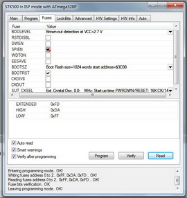
Click on the Fuses tab, the programmer will read the fuses automatically and show them:

Let's take them one by one, top to bottom:
BODLEVEL - any Arduino chip has this disabled, but after some people having problems, I set this to 2.7V
RSTDISBL - of you check this fuse, the reset pin will be a regular I/O pin and you will not be able to reprogram your chip unless you use a high voltage programmer. DO NOT TOUCH IT!
Do not touch the next fuses: DWEN, SPIEN, WDTON, EESAVE. If you need to know more about what they are doing, read the data sheet.
BOOTSZ - this is the space reserved for the bootloader, Arduino bootloader uses 1024 words, select that one
BOOTRST - this fuse tells the chip to jump to the bootloader section after a reset or power up, check it
CKDIV8 - this fuse divides the clock by 8, uncheck it so your chip will use the full 16 MHz
CKOUT - this fuse tells the chip to generate a clock out, leave it unchecked
SUTCKSEL - this fuse tells the chip what kind of clock will be used. select the last position in the scroll down list
This is how the fuses look for an Arduino chip:

And this is with the BOD enabled:

Click on the Program button and the programmer will burn the fuses.
Go to the Program tab:

In the FLASH section, where it says Input HEX file click on the ... button, browse to the Arduino-22\hardware\arduino\bootloaders folder and choose the "ATmegaBOOT_168_atmega328" file, then click on the Program button.
After you programmed the bootloader, you need to make sure is protected from an accidental erase. Go to the Lock Bits tab:

Change the BLB1 fuse to "LPM and SPM prohibited in Boot Section" and click the Program button.
You're done!
Go to the Arduino IDE and load the Blink sketch from the Example, Basic folder, select your board to "Arduino Duemilanove or Nano w/ATmega328", select your Serial port to where the USB-serial cable is inserted and click on the Upload button. The D13 LED will flicker and then it will flash once per second.
Now you have a brand new Arduino chip with the bootloader burned, ready for your exciting new project!