


2D Robot Mapping Software for autonomous navigation
Would like to share some details on a 2D Robot mapping software I am currently working on. I have including a video of a robot using a map generated by this software to autonomously navigate and simulate doing an office delivery. Will add new update showing the mapping software in action.

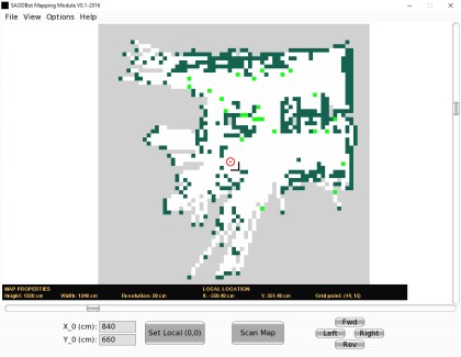
Mapping Module Graphic User Interface
- Main Menu - This contains the major operations that is possible with the program.
- Bottom Menu - The bottom menu contains frequently used commands. The includes access to the scan command and an option for setting the zero coordination reference point on the map. The point represents the zero or home position of the robot on the map in both X and Y direction.
- Map Area - The map occupies the central region of the program window. The Map consist of a 2D matrix with each cell in the matrix colored to represent a range of probability values:
- Probability values between 0.8 and 1 are represented by dark green cells. This area is occupied.
- Probability values between 0.79 and 0.51 are represented by neon green cells. This area is uncertain.
- Probability values between 0 and 0.49 are represented by white cells. This area is empty.
- The probability value of 0.5 is represented by gray cells. This area is unexplored.
- Map properties bar - The properties bar shows the important map properties such as height, width and resolution of the grid cells. The properties bar also shows the grid coordinate x and y value of the grid cell locator.

Grid cell locator and coordinates

File menu

View menu

Options Menu

New map dialog

- Table 1-7 outlines a summary of the mapping process. The process start with the creation of an empty occupancy grid map. To do this the width and height of the general area to be mapped, the size of the grid cell and the X and Y origin on the map is needed. All unit dimensions are given in centimeters. See the section on testing for the different map properties tested. The map is initialize with a probability value of 0.5.
- The next step involves the scanning of the area to be mapped with Ultrasonic, LIDAR-lite or infrared sensor mounted on a servo. This results in the capturing of a maximum of 180 points of measurement. The measurements are then converted from polar coordinates to rectangular coordinates then sent from an Arduino robot to the mapping software module. The module transforms each measurement points from Arduino's local frame of reference to Software grid map frame of reference.
- Next, for each measurement point which returns a probability of hitting an obstacle, the occupancy grid module traces all the grid points which are directly inline with it from the robot’s current location on the grid. It then calculates the probability of occupancy of each of the traced points. Entire grid cells are considered to be occupied or empty even if the obstacle being mapped partially occupies a cell. The resulting probability values are then processed and displayed visually by the Mapping module using the different color values discussed above. The process is completed when the entire area is scanned and represented by the occupancy grid.
Build an occupancy grid map from sensor data
- Actuators / output devices: servo
- Control method: manual
- CPU: Arduino, Raspberry Pi
- Operating system: Linux, Windows
- Programming language: Python
- Sensors / input devices: ultrasonic sensor, LIDAR-lite laser rangefinder
- Target environment: indoor