


The Big Wheel Bot design is centred around 2 x 250mm wheels with rubber tires. The wheels are mounted to a drive shaft using a 3D printed hub with captive nuts. The chassis plate has bearings mounted to it within 3D printed bearing housings to support the drive shafts. Two 12-24 DC gear motors provide drive to the wheels. The motor has a 3D printed drive gear attached to the output shaft and drives the wheel by meshing with an internal spur gear attached to the wheel itself. The image below shows one if the wheel spur gears.

The bearing housings and motors are attached to an aluminum chassis plate. Threaded bar is used to mount a battery plate and an electronics plate to the chassis plate, as shown below.

I tried several different gear ratios, with the biggest challenge being getting the gears to mesh reliably. I ended up using a lower gear ratio to get larger teeth on the gears help with the meshing. The below picture shows the drive arrangement with the drive gear meshed with the wheel gear.

For power I am using 2 x 12V SLA batteries connected in parallel to supply the motors. Originally I had intended this to be a balancing robot but after some testing I decided to add a rear castor and make this a 3 wheeled, differential drive robot. A 3D printed bracket attaches an aluminum box section to the rear of the robot that has a castor mounted to it.

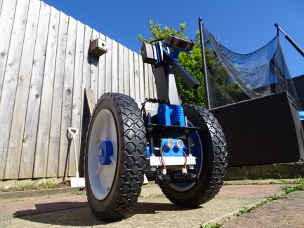
I have made some changes to the robot since the original post. I have redesigned the chassis to move the batteries behing the axel of the wheels, leading to a much more stable platform, particularly for driving around in the garden.
I have also added a servo driven robot arm to the wheeled base. I have attached the webcam to the arm to capture images for navigation as the robot drives around but also so that the camera can be moved to capture images of the plants in the garden. I will probably add a moisture sensor to the robot arm at some point. I have also put all of the electronics, including the Raspberry pi, into a plastic enclosure mounted to the top of the robot, to tidy everything up a bit. I have added some images of the redesigned robot below:


This robot uses an Arduino Nano to control the motors along with an L298 motor driver. The Arduino also gathers data from the 2 sonar sensors and an MPU6050 IMU. Below is the circuit I am using, minus the encoders which I haven't fitted to the robot at this stage.

The robot also has an on-board Raspberry Pi and a webcam for collecting video and logging data as the robot drives around.
The robot can be remote controlled by connecting to a HC-05 Bluetooth module connect to the Raspberry Pi. I have also built a homemade transmitter, again using an Arduino Nano and a HC-05 module to control the robot. Currently the robot can be remote controlled and video/data capture can be started and stopped remotely using the transmitter. The controller also features a 2.2" TFT display the I am currently using to display the joystick positions.The wiring diagram for the controller is shown below.

I have added some more functionality to the robot in the form of a servo driven robot arm and additional IR sensors. Below is the updated circuit diagram.

Below is my Youtube video showing more details of the development of the robot and initial testing.
Part 2 of the video series documenting the build of the Big Wheel Bot is below.
Part 3 of my Youtube series covering the Big Wheel Bot build can be found below.
Part 4 covers how I created an occupancy grid map of the garden, using data collected by the robot.
Part 5 shows my first steps towards using the onboard video camera for mapping. I can use the sensor data from the robot to plot the robots path in 3D and calculate the approximate camera poses for each packet of data.
Part 6 covers a rebuild of the robot chassis with improved gearboxes.
In Part 7 I started looking into alternative navigation strategies. This lead to me looking into the navigation techniques used by insects. To begin investigating I made a few changes to the robot and started modifying and building on the existing software. I wanted to automate the robot rather than rely on the remote control. I am now using the IMU to align the robot to a given orientation and drive in a straight line. I have also been experimenting with using the webcam to measure the distance that the robot has traveled, with some success. I have fitted a pan/tilt head to the robot to allow the capturing of images from several angles round the robot for future use.
I also made a Youtube video showing the construction of the transmitter.
Currently the robot is only remote controlled but I am working on automating the robot for autonomous navigation. At present I am using the robot to collect video and sensor data as it is remotely controlled and then working on this data offline from the robot.The transmitter is sending x and y data from both joysticks, on a software serial port to the HC-05 module, and also writing the joystick positions to the TFT display.
Most of the code is for outputting images to the TFT display using the Adafruit library which simplifies things greatly.
The Raspberry Pi receives the serial data from its HC-05 module and a python script echos this data to the Arduino on the robot. I chose to do it this way as it makes it easier to start and stop video recording remotely. The Arduino on the robot then calculates wheel speeds given the joystick position. The robot Arduino is also reading from the sonar sensors and the MPU6050.
The Arduino is sending data to the Raspberry Pi, via serial, at set time intervals. Every time the Raspberry Pi receives a packet of data, it triggers a frame of video to be captured, in an attempt to synchronize the data and the video for further work offline from the robot.
All of the code for this project can be found on Github here: https://github.com/BigFace83/Big-Wheel-Bot
In order for the robot to be useful in the garden, it will need a way to navigate to where it is needed. I have started work on creating an occupancy grid map from the data that the robot collects as it is being driven around the garden under remote control. All of the code for this project can be found here https://github.com/BigFace83/Big-Wheel-Bot
Below is an image of the type of map I have been able to produce.

I have added my latest youtube video to the video section that explains how the map was created.