


Explorer Robot Rover - Acerola01
***Project completely rewritten*** Version of January 28
0 - ONCE UPON A TIME... (A BRIEF HISTORY)
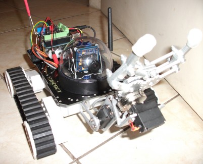
This is my first project, a explorer rover with robotic claw controlled at distance by radio control. I am calling Acerola01 because of the typical fruit from Brazil.
The objective this project is to learn and know the various devices and actuators that make up a robotic vehicle, such as Arduino board, software/sketch, interface boards, motor drives, motors, radio control, cameras, servos, etc, although this project is not to be called "a robot", because the software does not have decision process or autonomous navigation systems (not yet).
I started very simply, knowing the Arduino board, their characteristics and essentially mounting small academic projects. Of the research on the Arduino, was very fast to come into their robotic applications and obviously reach the LMR!
When I met the LMR, I felt like Neo taking the red pill offered by Morpheus. Phenomenal!
After additional research and a lot of navigation by the LMR site, I found it fun to learn building a robotic vehicle. Because of incidents in Brazil, I also saw possibilities very useful to use robotic vehicles to aid in rescue missions.
I decided to build some models and make "proof of concept" for the various modules that I thought to implement. From this point, I concluded to build my first model based on the Arduino board and a simple but robust platform that was the Dagu Rover 5 in its simplest version, 2 motors without encoders.
I - THE PROJECT
The main features and functionality for first version (Acerola01) that I thinking:
1. Platform simple and robust, primarily for indoor use: I enjoyed the Dagu Rover 5 platform, though other good options available. I have found a cheapest model at HobbyKing and it was important to my decision. :-)
2. Electronic control boards: I chose the Arduino board as the main control board. After some research, I concluded as good choice for motors control board to DFRobotics Motor Shields 2A.
3. Remote control simple and cheap: I chose a simple and inexpensive model radio control HobbyKing 6 channel, the HK-T6A V2.
4. Devices interact with the environment: Since the goal is an explorer rover, I installed a camera FPV for recognizing environments and control navigation. The system for transmitting and receiving video and audio signals used was Boscam 5.8GHz 200mW FPV Wireless. As additional, I put a robotic claw to perform missions and interact with the environment.
5. Power system: I googled about LiPo batteries, but I decided to use this first project, the simple and usual rechargeable NiMH batteries. But I'm programming an update of my energy system, changing to LiPo batteries and evaluate improvements in performance and uptime.
II - MOUNTING IT
1. PLATFORM
Well, Dagu Rover 5 does not need presentations, chassis is a recognized successful, very popular for use as robotic platform. I leave my congratulations to Russell Cameron (OddBot), designer of Dagu products and a great guy here at LMR. Special thanks to Fris Lyneborg (fritsl) who helped me register here and throughout his work in the LMR. And to all who share their projects and knowledge!

For those who want to know a little more about the chassis, follow the link to the manual and specifications of the Dagu Rover 5 here (Dagu Support website).
I used the mounting plate for tank chassis DFRobot (about this item and all other components that I used in the construction of Acerola01 Rover, are below in Chapter COMPONENTS), designed to fit a variety of sensors, controllers, power switchs and other devices. Well, the text in the picture is self-explanatory, is not it?


Wow, my Curiosity Mars Rover together with my fellow Darth Vader (above) in the background of the picture :-)
Below, mounting electronics into the Rover 5 platform:

2. ELETRONIC CONTROL
To drive the Acerola01 rover, I use two boards, the Arduino board and the 2A Motor Shield for Arduino, of DFRobot.


My objective is not to detail the operation of the boards, but I leave the links for those who want to know more about them, their technical specifications:
The mounting plate DFRobot has several holes that fit with the holes of the various models of Arduino boards. I set three standoffs in Arduino board and the motor shield board 2A DFRobot was placed on top of it, as we can see in the photo below. We can also see the original connectors of the motors of Dagu Rover 5 connected by me at the 2A Motor Shield DFRobot. I was doing some basic tests of the electronic connection:

In the photo below, we can see the entire electronics assembly for rover Acerola01, with the Arduino board together with 2A Motor Shield of DFRobot, the Boscam 5.8Ghz 200mW video transmitter (which has built-in microphone) on the right side and the left side in photo, the receiver 6 channel for the HobbyKing 2.4GHz radio control. Under the Arduino board can see a white part that is the 4 AA battery holder, which along with the other battery holder that I put inside the chassis, supply energy for all systems of the rover.

3. REMOTE RADIO CONTROL
I chose the 2.4GHz radio control with 6 channel Tx & Rx of the HobbyKing model HK-T6A V2 (throttle on the left) because I will control a rover (robotic ground vehicle), so I do not need right now a very reliable signal or long distance (not is as critical as helicopter control, for example). So it is possible to use quite well this radio control, that still has 6 channels and is good deal for the price paid (list of materials and prices are in Chapter COMPONENTS, below). For to get manual for this radio control, you can download here (original manufacturer FlySky that provides for the HobbyKing).

The receiver of the photo below is already in its final assembly, with all channels being used:

As beginner in radio control, I had much difficulty for knowing which stick, controlled which channel. I found no document specifying this and I had to find out making direct tests with each channel with a small program on Arduino. For those who are newbie like me, I hope that the identification of channels and controls below help:


As I already said earlier, I'm using all 6-channel radio to control all functions of Acerola01 rover. The photo above is easy to understand, but I will detail a bit more like the controls are configured:
- Channel 1: Turn left, turn right - If the rover has not command forward or backward, it will turn on its own axis, for direct or left, depending on the command in this channel;
- Channel 2: Going forward or backward, I wrote the software to vary the direction and speed (power on engines) according to more or less drive in this stick control;
- Channel 3: Tilting movement control, ie, regulates camera vision up or down. This stick is free, then it does not return to central position when it is loose;
- Channel 4: Panning/Panorama movement control, it allows you to move the camera sideways. Very useful for navigation and exploration with the rover;
- Channel 5: I am using this channel, the upper right knob on my radio control transmitter HK-T6A to control opening and closing of the robotic claw;
- Channel 6: Knob upper left of my radio control transmitter HK-T6A used to control the lifting or lowering of the arm that controls the robotic claw.
Watch the video where I recorded the movements of the camera on pan/tilt (channels 3 and 4) and movement of the robotic claw (channels 5 and 6) here.
Watch the video where I recorded with the direction control of the rover (channels 1 and 2) here.
4. DEVICES & ACTUATORS
In this chapter DEVICES & ACTUATORS I highlight two items that comprise important features of Explorer Rover Acerola01. It is the functionality of vision in First Person View (FPV) received by wireless through the camera 1/3 inch that can to move in pan & tilt, and another important feature that is interacting with the environment through its robotic claw which can grab objects and move them from place. So, it is can explore environments and develop missions for Acerola01.
4.1. CAMERA SET
The camera set includes: 1/3-inch SONY CCD Video Camera (NTSC), 2.1mm F:2.0 Turnigy Micro FPV Camera Lense that I changed (it's worth, increases the field of view, very helpful in navigating of rover with camera), the FPV Fiberglass Pan-Tilt Camera Mount with your 2 micro servos HTX900 and Boscam 5.8GHz 200mW wireless Tx & Rx set.
It is important to remember at this point that this whole project was worked prioritizing low-cost solutions. Like everything in life, it is important to note that cheap product will not give the performance of other product of better quality that is more expensive obviously.
a. 1/3 inch SONY CCD Video Camera (NTSC)

Sorry for the image of the HobbyKing, I did not take pictures from my camera before mounting.
From the research I did, this camera seemed like the best option for resolution, pixels and other features, and its price. Main features (from HobbyKing site):
- Image device: 1/3-inch Sony super HAD color CCD
- Pixel: 752 x 582(NTSC)
- Horizontal resolution: 520TV Lines
- Minimum Illumination: 0.1Lux/F1.2
- Lens: 3.6-6mm
- Input voltage: DC12V
- Size: 38 x 38
- Power supply: 12V/150mA
Set of cables from the camera & Boscam 5.8GHz transmitter below. I recommend perusing the "official" documentation (yes it's confusing) of the camera and video transmitter Boscam, but hopefully help with the following information (and not further confuse!):

Still on the camera, I bought a 2.1mm F:2.0 lens (below) to replace the original lens of micro camera Sony. I had doubts but I made an excellent purchase (lucky, haha) because this lens greatly increases the field of view which helps a lot in navigation and execution of missions.

Sorry again for the image of the HobbyKing, I did not take pictures from my camera before mounting.
b. FPV Fiberglass Pan-Tilt Camera Mount L-Size (and 2x HTX900 9g Micro Server)
I chose the following model pan/tilt support for being small, compact and light and I used along with this support, 2 micro servos often used by hobbyists who is HTX900 9g. Care is necessary in choosing the pan/tilt bracket. It is important to check the dimensions of the micro camera with support because I almost bought wrong!


If you want additional technical information of HTX900 servo, see here.
Below we can see the base of the dome that I had to adapt because it is of security camera and not robotic applications. Despite the need for mechanical adjustments, got very good size of camera with the dome, perfect! (lucky again, not sure it would work...)


In the picture above we can see the assembly of micro servo for movement of tilting (vertical movement) and below we can see mounted underneath the base of the dome and already embedded in the mounting plate for Tank chassis DFRobot, another micro servo which is responsible for panning, the horizontal movement of the camera.

c. Boscam 5.8Ghz 200mW FPV Wireless AV Tx & Rx Set
I researched on the systems of transmission and reception of video for FPV - First Person View and I found 4 main frequencies used and sold: 900MHz, 1.2GHz, 2.4GHz and 5.8GHz. Of surveys, concludes the choice of systems 5.8GHz and with it, bought a set Tx & Rx Boscam, 200mW. Of existing options is one of the lowest power available but I chose it to test the coverage offered before buying any other model of greater power. In my indoor tests, with walls and obstacles, I could not more than 8 to 10 meters away with the image. But this is not conclusive yet.

Transmissor Boscam 200mW main specifications (*):
Video Format: Pal/NTSC
Output impedance: 50Ohm
Output power: 21~23dBm
Channels: 8
Transmitter operating voltage: 7~15VDC / 150mA
Dimensions: 55x26x17mm
Interestingly, the camera has no microphone and this transmitter Boscam has built-in microphone.
The video receiver is a Boscam RC-305 with 8 channel. It contains an additional output audio/video that can be used to connect directly a recording device without disturbing the audio output and the main video. Pay attention because the receiver requires a 6.5VDC to 12VDC (*) power supply not included in the set and its power supply connector is less than the standard.

Video receiver Boscam RC305 main specifications (*):
Channels: 8
Receiver operating voltage: 5VDC (the correct is 6.5v to 12v - my note)
Operating temp: -10~85C
Video bandwidth: 0~8.0MHz
Audio frequency: 6.5MHz
Weight: 43g
Dimensions: 61x52x13mm
Look below detail of dip switch in RC305 for reception channel change:


We can see from the photo above the 5.8Ghz transmitter Boscam set in Acerola01 rover with the antenna raised sideways, a solution of design and functionality which in my opinion was pretty cool ;)
And below, we see the Boscam receiver, which should stay in operations base and control the rover through the images received remotely for navigation and development missions.

(*) The product is good but the documentation is awful. Much confusion so I will not suggest any link to check technical specification, sorry. I suggest caution in using the technical specifications. Anyway, the technical specifications of Boscam 5.8GHz Tx&Rx were obtained from the HobbyKing website here.
d. Mounting the camera set
Well, I have enough photos of camera mounted on pan-tilt support and the two micro servos HTX900. My tip is to do in a time when you are calm because it is very small and delicate mechanical assembly.

The photo below shows where it hides much of the wiring of the rover. Highlight in yellow, a little secret, mounting brackets that are creating a gap between the platform Rover 5 and the mounting plate DFRobot. This space is important for passing part of the holder batteries cables and robotic claw cables that can enter inside the chassis and go directly to the receiver of the radio control.

Picture of tilt movement servo in support of pan/tilt. Sorry for the poor image quality:

Almost done!

4.2. ROBOTIC CLAW
This is a typical and popular set of mounting Dagu, the Robotics Claw MKII. There is extensive documentation on your assembly on the internet. If desired, follow the link on the Dagu MKII here. The pdf file is large (105MB) but not because of being an extensive manual (only have 5 pages), it is more because of the high resolution photos (Odboot, this could not be easily solved?). There is a modicum of difficulty, but the assembled kit is very cool and fun!


And finally...

Dad, I'm ready!
5. POWER SYSTEM
One of the valuable lessons that I take from this project is the importance of the power supply of the rover. I had almost a whole day worried about the camera that stopped working, I took apart almost the entire rover, the camera, the Boscam transmitter, the receiver, to find it was problem with the batteries (I connected directly into a good power supply and returned to work made magic!).
I use 8x AA rechargeable batteries NiMh giving a total of 8 x 1.2V = 9.6V. I'm using 8 batteries because the camera specifies 12V supply. The camera is operating with 9.6V and Dagu Rover 5 motors, which specifies 7.2V, has also worked without problems (do not know the long-term consequence of this surge in the motors, but now, it's ok).
A design solution for Acerola01 rover was put 4 batteries internally, in a similar to the original configuration of the Dagu Rover 5, and other 4 batteries in the space below the Arduino Board.

This solution leaves the Acerola01 rover with a good weight distribution, beautiful and elegant with just 4 batteries out, under the Arduino Board. But created a small problem which is the need to disassemble the mounting plate DFRobot to take the batteries every time it is necessary to recharge them.


Another problem I had was that I found the weak holders to put inside the rover. I made a replacement for a holder equal to the external batteries by placing in the middle of inside the platform.

On the question of disassembly the Acerola01 Rover to take the batteries to recharge, I did some testing load directly by the DC connector.

Like a gas station...

Like a gas station is cool, but I need to study and research more about NiMh battery charge. The information on Sony Battery 2500mAh CycleEnergy, it marks charge of 230mA for 16 hours. I did some testing with charge 12v but limiting the current at 200mA. I don't monitored the time but I need to know how to charge the batteries without disassembling the rover.
I am awaiting my request for LiPo battery and charger, which also charging NiMh batteries, we'll see how it behaves being charged by smart charger (hope it's clever!).
6. OPERATION/CODE
To drive Acerola Rover, the signals of channels 1 and 2 of the radio control receiver, are read and converted in the Arduino to the PWM signals that go to the DFRobot Motor Shield board. The code written by me allows total speed control and direction. To learn more, see the video from direction control or if you want to analyze, improve and use the code that I wrote, you can see here (it's in txt, I understand that is easier to read all the code)
III - COMPONENTS
Dagu Rover 5 chassi, 2 motors without encoders: US$ 27.34
DFRobot Tank platform upper deck: US$ 8.00
Auduino Uno R3 ATmega328 board: US$ 11.03
2A Motor Shield for Arduino - DFRobot: US$ 16.00
Radio Control 2.4GHz 6ch HobbyKing HK-T6A V2 Tx&Rx: US$ 25.07
1/3 inch SONY CCD Video Camera (NTSC): US$ 31.93
2.1mm F:2.0 Turnigy Micro FPV Camera Lense: US$ 9.15
FPV Fiberglass Pan-Tilt Camera Mount L-Size: US$ 4.99
HTX900 9g Micro Servo: 2x US$ 2.69 = US$ 5.38
Boscam 5.8Ghz 200mW FPV Wireless AV Tx & Rx Set: US$ 54.99
Dome (Brazilian store): R$ 4.90
Robotic Claw - MKII: US$ 11.95
Robotic Claw Pan/Tilt Bracket - MKII: US$ 29,95
Servo to Robotic Claw - DGServo S05NF STD: US$ 10.95
Battery Holder 4xAA: 2x US$ 1.95 = US$ 3.90
Battery AA Sony 2500 mAh CycleEnergy NiMh: 2x (4-pack) US$ 15,94 = US$ 31,88
TOTAL this items: US$ 287.41 (no shipping cost).
IV - CHALLENGERS
- Reduce noise in the video - quite improved after replacing the cable with a shielded and shorten the size;
- Improve rover driveability (via improvement in software). There are mechanical limitations and small problems in the structure of Dagu Rover 5, on its axis and the rubber tracker which loosens, mainly in outdoor use;
- Test video signal improved and increased distance with Cloud Spirit Circular Polarized Antenna;
- OSD implementation;
- Adding sensors to risk assessment;
- Change power system for LiPo batteries.
V - FINISH
I apologize for my "Google Translation" English and handwriting errors.
Corrections, comments and suggestions for improvement are very welcome!
I thank those who post here constantly in the LMR because from the projects that I read, I rode my own.
This post was long, boring and tiring, but hopefully help some as I was helped here in LMR. And serves as my journal for future reference.
Thanks all!
Explorer robot with camera 1/3 inch and pan-tilt controled by radio control
- Actuators / output devices: pan and tilt system for camera, robotic claw
- Control method: 6 channel RC 2.4GHz radio controlled
- CPU: Arduino Uno R3
- Power source: 8x AA NiMH batteries
- Programming language: Arduino ide
- Sensors / input devices: micro camera 1/3 inch Sony CCD
- Target environment: indoors mainly