


WALTER - The Arduino Photovore Insect Robot
[Please excuse my English]
I really like the popular set-up of 2 servos arduino insects on youtube. When I looked at it, I always remember what BEAM robotic guys did long before that set-up became favorite. These people who are analog robot fanatics did better on the gait due to better angle between the two motors (microcore / bicore walker , etc).
However, in my opinion, none of those mentioned before look more alive than VBug1.5 (also known as Walkman) created by the founder of beam robotic, Mark Tilden. It’s using 5 motors, therefore it has more maneuverability. Making a simple BEAM robot is not difficult, but building something as complicated as VBug1.5 could be distressing for an electronic novice like me. So, when I decided to make something like Tilden’s bugs, I had to settled with arduino platform, the easiest choice for non-engineers (or in my case, embarrassingly, an engineer wannabe).
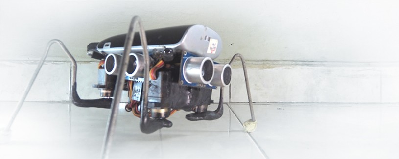
As a result, I made Walter, a 4 legged arduino robot with 5 servos. You may wonder, if I wanted to make a look-alive bug robot then why I didn’t go with 8 or 12 servos instead. Well, I was thinking something simplest I can do to get most maneuverability I can have. I’m talking about using a lot of glue instead of making frames.
BEHAVIORS
Like many other arduino robots, Walter can avoid obstacles using HC-SR04 ultrasonic sensors. To add character as a bug, Walter also a photovore, means he is attracted to light. Photodiodes are used to detect light. There are random values generated in the arduino sketch to make Walter decides when he wants to stop to rest, and also to randomly changes his gait speed (3 speeds).
When I started, I intended to have tact buttons under each of Walter’s feet so he would have a surface sensors. But the battery (a portable power bank for smartphone) costs the servos to much weight. I know tact buttons weigh almost nothing to worry to add weight, but ironically the weight of the robot is not enough to able to pressed the upside-downed buttons.
I planned to make Walter version 2 with bigger servos and then included these buttons as surface sensors.
BILL OF MATERIALS
- Controller: Arduino Pro Mini (5v, 16 MHz)
- Sensors:
3x HC-SR04 Ultrasonics Sensors
4x Photodiodes (5mm) - 4x 100kΩ Resistors
- Actuators: 5x MG90S Metal Geared Micro Servos
- Power: 5200mAH Portable Power Bank for Smartphone (2 chnnel output, 1A and 2.1A
- Some wires and female header connectors
- 2x USB A connectors
- Toggle Switch
- Coat hanger or any thin metal rod you can bend to make legs
- Glues (hot glue gun, super glue, and palstic steel epoxy)
At first I used white polymorph plastic, but then I switched using a lot of plastic steel epoxy. They're easier to use.

Many of these photos taken before I switched to plastic steel. Notice the amount of glues used. I meant it when I wrote glues are essential before.

The shaft is made from servo horn and spacer glued together.

I found a convenient way to put header connectors on arduino pro mini without soldering them to proto board or any pcb.

I also used spacer as a stand to hold the arduino pro mini and ultrasonic sensors.


2 USB connectors glued together with toggle switch. The USB's would then connect to 2 channels of power bank. Although the power bank has power button itself, the button can only turn the power bank on and start open the current, but it can't cut its current itself. Hence I added a toggle switch.

Here You see the legs had redone with plastic steel epoxy.

Here is an easy set up of my photodiode and resistor. No pcb, only wires and female headers needed. Sorry I missed taking picture details of the photodiodes glued to power bank.

First time fully assembled.

More details about Walter is here.
Navigate around and seeking light
- CPU: Arduino pro mini
- Programming language: Arduino C++
- Sensors / input devices: photodiodes, HC-SR04 Ultrasonic Sensors
- Target environment: my room